Table Of Content
They provide a simple and intuitive way to plan and communicate the structure of databases, making them valuable tools for developers and designers. Sometimes, engineers will branch out ER diagrams with additional hierarchies to add necessary information levels for database design. For example, they may add groupings by extend up with superclasses and down with subclasses. A Relationship Type represents the association between entity types.
History of ER Diagrams
You will first identify the entities and then create the detailed data model with actual table structures. ER diagrams are essential tools for designing, communicating, maintaining, and optimizing databases. They facilitate collaboration, ensure data integrity, and contribute to the efficient management of database systems. In the 1990s and 2000s, with the rise of the internet and new technologies, ER diagrams adapted to accommodate these changes. They continued to be essential for designing databases, but they were sometimes used alongside other modeling techniques. ER diagrams were first introduced by a computer scientist named Peter Chen in 1976.
See why teams use Lucidchart to create ER diagrams
I Love My Job: ER Doc and JeffDesign Director Bon Ku - Philadelphia magazine
I Love My Job: ER Doc and JeffDesign Director Bon Ku.
Posted: Thu, 13 Jul 2017 07:00:00 GMT [source]
This online ER Diagram tool lets you insert entities by copying SQL codes to a text file and importing them. It does not provide a feature to generate SQL script from the diagram, so consider this more of a drawing tool and not a full database modeling tool. You can start your data model from scratch or use a template.
ERD notations guide
Over and above, you may continue editing diagrams to integrated productivity programs like Jira and Confluence. Simplify ER diagrams with templates, dedicated shape libraries, and drag-and-drop, standard ERD symbols that allow you to build physical and conceptual ERDs in minutes. Include tables, fields, and primary or foreign keys, then connect each entity with specific crow’s foot notations to indicate the cardinality or ordinality of each entity. By defining the entities, their attributes, and showing the relationships between them, an ER diagram can illustrate the logical structure of databases. This is useful for engineers hoping to either document a database as it exists or sketch out a design of a new database. The Entity Relational Model is a model for identifying entities to be represented in the database and representation of how those entities are related.
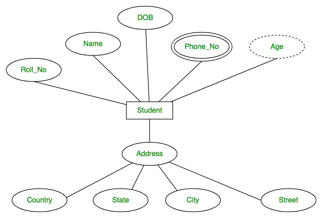
The order item will be meaningless without an order so it depends on the existence of the order. In this database, the student will be an entity with attributes like address, name, id, age, etc. The address can be another entity with attributes like city, street name, pin code, etc and there will be a relationship between them. If you have an existing database you need to document, you can create a database diagram using data directly from your database.
Play with New Ideas, Minus Drawing Time
They’re most often used to design or debug relational databases used for software engineering, business information systems, education, and research. They mirror grammatical structure, with entities as nouns and relationships as verbs. An Entity Relationship Diagram (ERD) is a visual representation of different entities within a system and how they relate to each other. It is a tool used to design and model relational databases, and shows the logical structure of the database. ER diagrams use symbols to represent entities, attributes, and relationships, which help to illustrate the relationships between the entities in the database.
Step Relationship Identification
Are you looking for a Free ERD tool for creating data models faster, easier and quicker? Visual Paradigm Community Edition provides you with an ERD editor for database design. It is an international award-winning modeler, and yet it is easy-to-use, intuitive & completely free.

How to Make an ER Diagram Collaboratively with Creately?
ER Yacht Design Reveals 61-Metre Sport Yacht Concept - Boat International
ER Yacht Design Reveals 61-Metre Sport Yacht Concept.
Posted: Tue, 03 Dec 2019 08:00:00 GMT [source]
Entities are represented in ER diagrams by a rectangle and named using singular nouns. This ER diagram tutorial will cover their usage, history, symbols, notations and how to use our ER diagram software to draw them. We’ve also added some templates for you to get started quickly. Chen's entity relationship model is in many ways the foundation for later practices like Unified Modeling Language or UML in information systems. Today we're going to walk you through everything you need to know about ER Diagramming. By reading this ERD guide, you will get the essential knowledge and skills about ER Diagrams and database design.
Automatic foreign key generation
A physical data model elaborates on the logical data model by assigning each column with type, length, nullable, etc. Make sure the column types are supported by the DBMS and reserved words are not used in naming entities and columns. An ER diagram presents a graphical representation of entities and the connections between them. Accordingly, a software program that enables users to build and edit ER diagrams is known as an ER diagram tool. For building and modifying the various elements of an ER diagram, like as entities, characteristics, and relationships, these tools often offer a user-friendly interface.
It’s relatively uncomplicated and simplifies your database development process. You can design conceptual, logical, and physical data models and then apply them to your database with just a few clicks. ERD is short for entity-relationship diagram; they are also known as ER diagrams. An ERD is a graphical representation of how to store data within a system; it shows the entities that hold data and the relationships between entities.
By the 1960s and 1970s, Charles Bachman (above) and A.P.G. Brown were working with close predecessors of Chen’s approach. Bachman developed a type of Data Structure Diagram, named after him as the Bachman Diagram. The work of Chen, Bachman, Brown, Martin and others also contributed to the development of Unified Modeling Language (UML), widely used in software design. A set of relationships of the same type is known as a relationship set.
Ray Chan, a longtime production designer on some of Marvel‘s biggest films, died this week, according to a statement Friday from Marvel Studios. We’re here to offer guidance and comfort throughout the process. If you have a minor injury or illness, such as flu or a sprain, you may not need emergency attention.
He proposed them as a way to visually represent the structure of databases. During the late 1970s and early 1980s, ER diagrams became widely used in both academic and industrial settings. They provided a clear way to show how different pieces of information are related to each other. ERDs can also be used to design and model new databases and make sure that engineers can identify any logic or design flaws before they're implemented in production. In system analysis and design, Data Flow Diagram (DFD) can be drawn to visualize the flow of information within system processes. In a Data Flow Diagram, there is a symbol called Data Store, which represents a database table that provides the information needed by the system.
Intelligent diagramming allows you to quickly visualize projects and processes from start to finish. Entities are depicted as rectangles, and relationships are shown as diamonds. Lines connecting entities and relationships represent the connections between them, often indicating the type of relationship (such as one-to-one, one-to-many, or many-to-many). Here's an example of a very basic database structure generated from data.
These are some of the best and free ER diagram tools to get the job sorted. In other words, you can sketch ERD using the drag-and-drop interface. On that note, if you prefer to create ERD without leaving your keyboard, the latter solutions are the right fit.
A many-to-many relationship refers to the relationship between two entities X and Y in which X may be linked to many instances of Y and vice versa. The figure below shows an example of a many-to-many relationship. Note that a many-to-many relationship is split into a pair of one-to-many relationships in a physical ERD. Lucidchart lets you easily create ER diagrams, with smooth placement of shapes, lines and labels. With all editing taking place in the cloud, it’s easy to collaborate with colleagues.


No comments:
Post a Comment